I have decided to opt in for using the Arduino Nano for prototyping and the STM32 "Blue Pill" board for when time eventually comes to deployment. Why?
- The Nano has a serial port and good debugging infrastructure around it, I can easily send data back to the computer and plot things.
BUT:
- The Nano is slow. Its ATMega with a 16MHz clock cannot really compete with the STM32 (72MHz). We will be doing plenty of number crunching on these little guys!
- The Nano outright cannot generate a clean square wave of 100 kHz. Maximum it can do is a fraction of that. On the other hand the STM32 can easily do that and much, more more, its theoretical maximum is 32MHz!
- The Nano has abysmal SRAM at 2KB. The STM32, while still constrained, is much better with 20KB. We need to store a lot of the data points in memory to do demodulation.
- The Nano has a 10-bit ADC while the STM32 has a 12-bit one, meaning a 4-fold increase in the number of voltage steps. Who would say no to more precision? If not for the first point I would directly build this thing on the STM32 board but we are dealing with something that will probably take a lot of visualizing and debugging to conceptualize, and that doesn't seem easy to do by hooking up an LCD or probing with a (cheap) multimeter when dealing with kHz frequencies.
Let's start with the old classic: blinky. It turns on an LED for 1s, turns it off for 1s and repeats. We will use the exact same wiring for this as we did for the RC timer (including the middle tap, now between the resistor and LED) but for testing we will insert an LED instead of a cap and BOOM, blinky.
#define SIGNAL_PIN 9
#define SENSE_PIN A0

void setup() {
	pinMode(SIGNAL_PIN, OUTPUT);
}

void loop() {
	digitalWrite(SIGNAL_PIN, HIGH);
	delay(1000);
	digitalWrite(SIGNAL_PIN, LOW);
	delay(1000);
}
Let's get fancier and continuously measure the voltage drop across the LED now with our extra sophisticated wiring (one jumper to A0). But wait, we cannot do that currently, why? Those pesky delays! They block the control flow, so we cannot use them while also getting other measurements without doing fancy embedded stuff. (interrupts)
So we'll do the following:
#define SIGNAL_PIN 9
#define SENSE_PIN A0

void setup() {
  pinMode(SIGNAL_PIN, OUTPUT);
}

static uint64_t s_last_toggle = 0;
static uint8_t s_toggle_state = LOW;

void loop() {
  uint64_t u = micros();
  if (u > s_last_toggle + 1000000) {
    s_last_toggle = u;
    s_toggle_state = !s_toggle_state;
    digitalWrite(SIGNAL_PIN, s_toggle_state);
  }
}
With this we keep our own record of how much time has passed and deal with events accordingly. Therefore we can sample data and toggle the pin when the time comes at the same time. You should be familiar with this flow if you have done any sort of computer graphics/gamedev work.
Full measurement code:
#define SIGNAL_PIN 9
#define SENSE_PIN A0
#define SENSE_R 994
// MEASURE WITH MULTIMETER
#define REFERENCE_V 4.49f

#define STRINGIFY(A) #A
// We do this because even in this great year of 2025 the Ardiuno IDE Serial Plotter
// does not support setting bounds for the y-axis (or anything else really)
#define SERIAL_PLOTTER_Y_BOUNDS(lower, upper) Serial.print("Min:" STRINGIFY(lower) ",Max:" STRINGIFY(upper) ",Value:")

void setup() {
  pinMode(SIGNAL_PIN, OUTPUT);
  Serial.begin(9600);
}

float calculate_vcc(uint16_t count) {
  return ((float)count / 1023.0f) * REFERENCE_V;
}

static uint64_t s_last_toggle = 0;
static uint8_t s_toggle_state = LOW;

void loop() {
  uint16_t count = analogRead(A0);
  float vcc = calculate_vcc(count);

  SERIAL_PLOTTER_Y_BOUNDS(0, REFERENCE_V);

  Serial.println(vcc);
  uint64_t u = micros();
  if (u > s_last_toggle + 1000000) {
    s_last_toggle = u;
    s_toggle_state = !s_toggle_state;
    digitalWrite(SIGNAL_PIN, s_toggle_state);
  }
}
As we can see, there is 2.38V across the LED when it is energized, which is pretty close to the reported 2.2V drop for green LEDs like this. But do you see that slope? Isn't it supposed to be a step function? Well, yes but this is really a limitation of the microcontroller, it uses something called a capacitive sample-and-hold circuit to take analog readings. There is essentially a tiny capacitor in there that gets charged in there. But this capacitor is tiny (like 14pF) so you don't exactly see that RC characteristic that we saw with the RC timer tool due to precision, and thats right, more parasitics.
Let's try a 220uF cap.
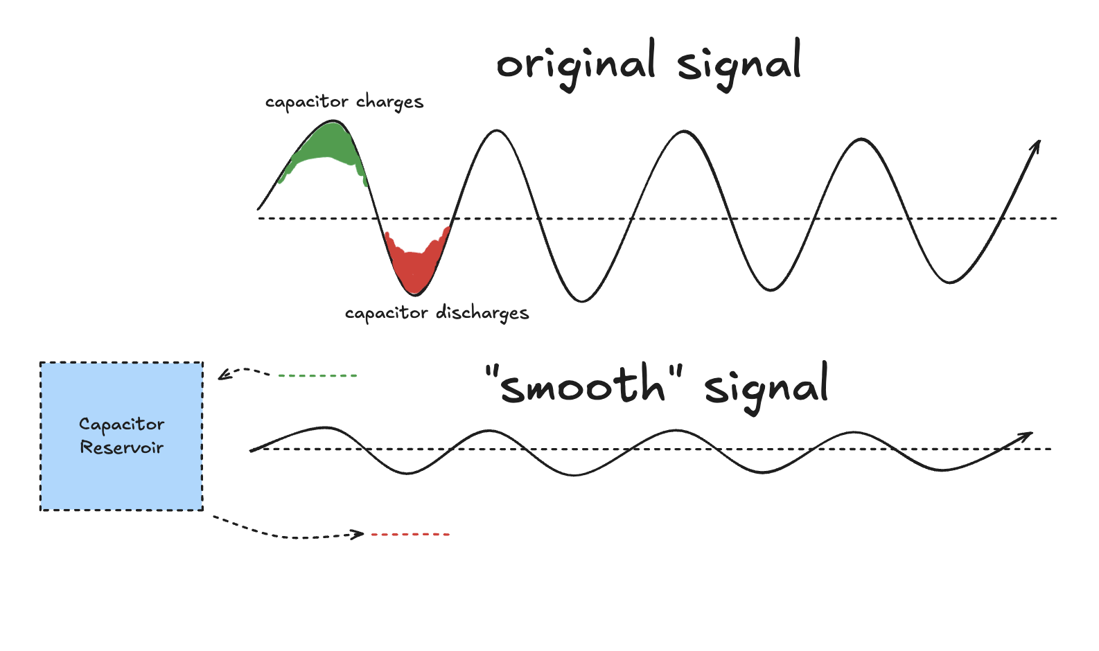
 There we go! That is a familiar shape. Though we already know how the graph is at really low frequency (0.5Hz in this case), so let's look at how it changes at high frequency when we don't give the cap enough time to charge. I'll plug in 4 caps of various capacitances.
As we can see, the capacitor ends up "smoothing out" the voltage. This is because the capacitor absorbs energy at the peaks and gives it back during troughs.
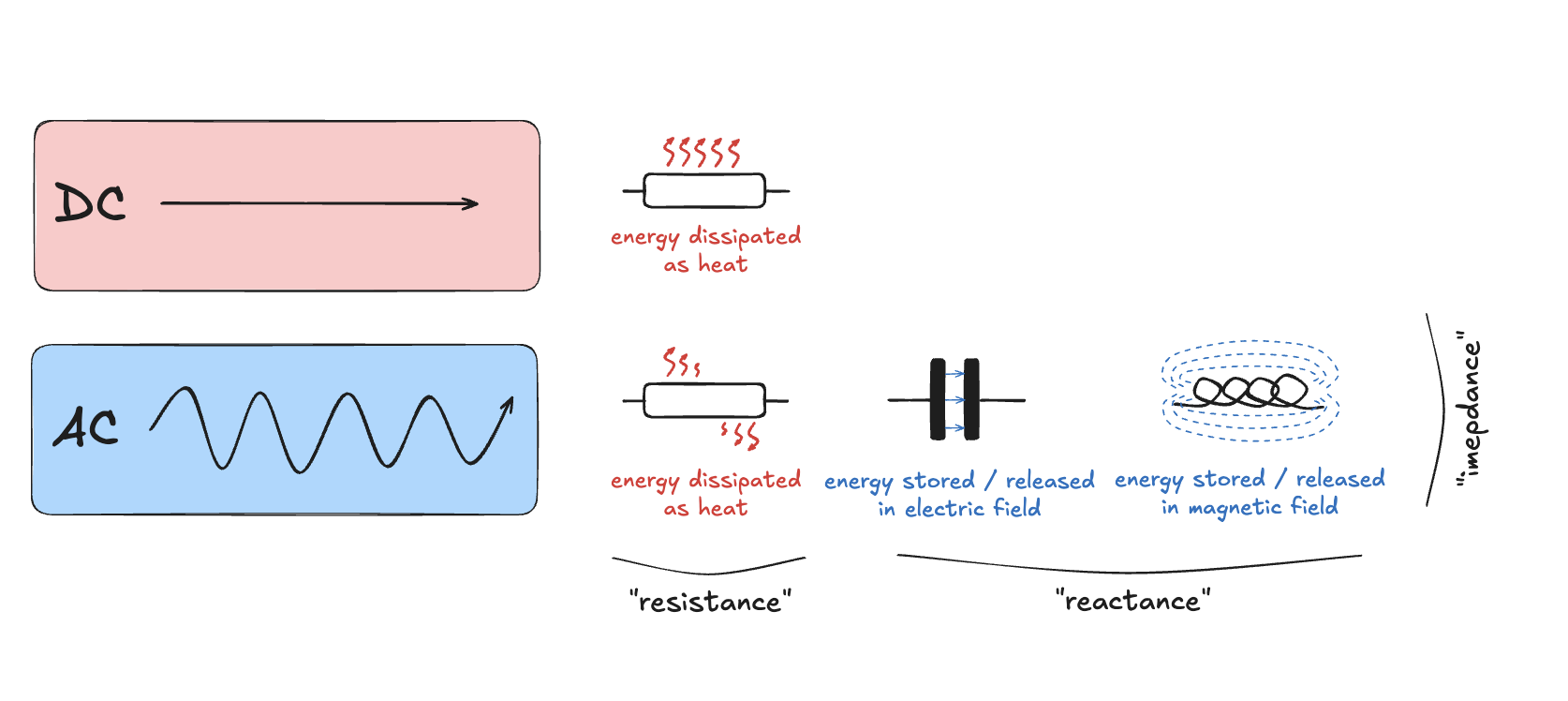
Now this part is really important, an I am glad that I understand this now. People throw around the word impedance a lot; they usually described it as "resistance for AC" but that is quite a reductive way of looking at things I believe.
To talk about impedance, we first have to talk about reactance. Don't worry the jargon soup stops about now.
Reactance is usually defined as the resistance-like characteristic exhibited by capacitors (and inductors, more about them later). What does that mean? Well, they lower the RMS voltage and current WITHOUT consuming power. But, how? A resistor does that by literally dissipating electrical energy away as heat, but how about these components? The answer is exactly how a capacitor smooths voltage out, it has to do with the same "strategic" charging and discharging reactive components (like caps) do to make voltage "seem" lower. The peak-to-peak voltage (proportional by a factor of uh, something, to the RMS voltage) is simply lower when the cap smooths it out!
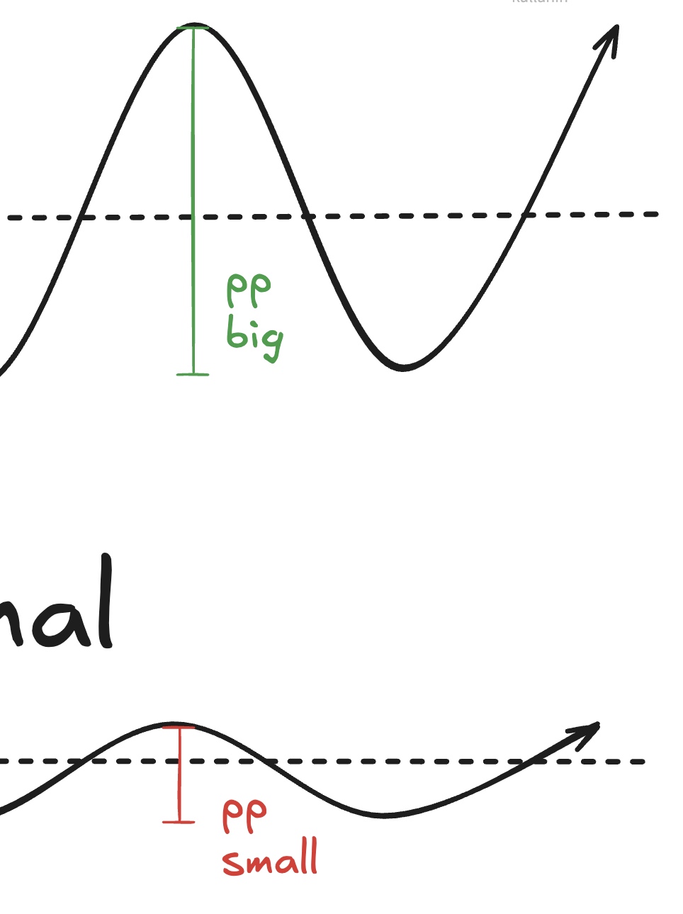
So the capacitor reacts and acts accordingly to the state of the AC wave to charge and discharge "strategically", hence the name reactance. By doing so it actually ends up reducing the peak of the voltage wave allowing less current to pass through, so it is also impeding the flow of current. A resistor also impedes but does so by means of a less sophisticated method (heat, heat, heat), so it is still resisting.
A CAP "SMOOTHING OUT" A SIGNAL MEANS THE SAME THING WHEN IT IS "IMPEDING" VOLTAGE! Bigger cap <=> more smoothing <=> more reactance
Reactive components (capacitors and inductors) let the "impeded" voltage bounce like a standing wave ideally consuming no power
Hopefully that clears some stuff up about impedance (it did for me).
Erratum
Turns out I got a bunch of things wrong here. The capacitor smoothing <=> reactance thing is very much baseless and just my pattern matching abilities going a little too far. I am not exactly confident in their deeper workings now but capacitors do have reactance and impede current. In fact if you have a bigger capacitor it impedes less (lets more current flow) because C is inversely correlated with capacitive reactance. The smoothing thing has more to do with power electronics (the first time I met capacitors) and analog filtering. Anywho the equations below are correct.
An important thing about impedance, we don't just add up resistance and reactance to come at an impedance value. This is because resistance is like apples and reactance is like oranges; one impedes by actively dissipating energy and the other does so by storing it. So impedance is really a two element vector of apples and oranges resistance and impedance so that you can describe the whole impeding behavior as its two base components.
Most often you see this vector represented as a complex number with a real component (resistance) and an imaginary component (reactance). This isn't because the square root of one has etherial influence on our laws of physics or anything; it is just a convenient way to represent 2D vectors because the math prospects of $i$ lets us do vector-y things without technically bothering with two distinct real numbers.
$$Z = R + iX$$
Confronting Reality
Now here comes a fact that I can't just put inside a reality hammer popup: real capacitors are not ideal capacitors (shocking). What this means in practice that they are not these magical devices that have an exact C value and absolutely no parasitic resistance and inductance. However, real capacitors have all three because they are physical objects made of real materials with characteristics. The cherry on top is that these parasitics change with the given AC frequency. Though for probing we can fix a frequency of 100 kHz (this meter and commercial meters) and at that low of a frequency we can mostly ignore the parasitic impedance. The resistance (called the equivalent series resistance, ESR) is a really useful thing to know because it can screw up with tuning among other things.
That resistance is quite low for a reason (< 10 ohms worst case) because people want capacitors that don't glow in the dark. You can't measure it with a cheap multimeter because it applies a DC voltage to the cap, charging it and eventually making it act like an open circuit. The RC timer approach for this doesn't work either because the sense resistor is just too damn big to capture the measily small ESR. Also good luck algebraically separating it from C with all that noise.
Our good friend impedance comes to save the day here! However, before we talk about it, let's first see the reactance formula for capacitance: $$X_C = \frac{1}{2\pi f C}$$ It essentially says that capacitive reactance is inversely proportional to the capacitance of a capacitor. It also says that higher frequencies result in less reactance. This is because at high frequency the direction is just changing so fast that the poor cap doesn't have time to charge up and down to impede anything.
We literally model the real world capacitor as an ideal capacitor plus an ideal resistor representing the ESR. Therefore the total impedance of capacitor looks like this:
$$Z = R_{ESR} + i\frac{1}{2\pi f C}$$ We want to know $R_{ESR}$, and we have a really cool trick to pick it out. If we pick $f$ to be really large (say, infinity), then that reactance term will just go to zero and we'll be left with $R_{ESR}$! Of course in reality we cannot do infinite frequency, but we can pick a relatively high frequency (say 100kHz) then we can essentially consider that term to be insignificant next to $R_{ESR}$.
Details
You might have realized that I initially referred to 100 kHz as "low frequency" while referring to it as "high here". Context matters! The sort of frequencies used in RF applications like radio control or WiFi is on the order of high MHz to GHz. 0.00001s per cycle is quite fast when you consider it on its own but is virtually nothing compared to other applications. So it is considered low frequency (LF). For this use case though it is perfectly adequate to eliminate the reactance.
So with $f >> R_{ESR}$ $$Z \approx R_{ESR}$$ Also $R_{ESR}$ is, again, a really small quantity, so at low frequency where the reactance dominates: $$Z \approx i\frac{1}{2\pi f C}$$
With this new information, here is our game plan:
- Generate a low frequency (100Hz) and a high frequency (100kHz) signal from a microcontroller
- Pass it through a capacitor with a sense resistor to not screw up precision similar to a voltage divider
- Measure the impedance by using the voltage reported on the ADC
- Do digital processing with it (Demodulation?)
- ???
- We get to know $C$ and $R_{ESR}$!