This is a really quick way to quickly put together a C (capacitance) meter to get decent readings and maybe to get that dopamine boost from seeing numbers show up on a screen (some people are weird like that, right?).
Though seriously, I feel like this method is underappreciated. I often see people showing how to measure C with signal generators while they could just throw this simple circuit together with a Nano to get decent readings.
Voltages and dividing them
A DC voltage source, when shorted, will dump INFINITE current on the wires it passes current through. This is never the case of course, both because the voltage source has a nonzero internal resistance and the wires themselves are not superconductors. But for most hobby applications we may as well just assume they are ideal.
We use resistors to reduce current. Let's say that we have a load that has a resistance of 10 Ohm and a continuous power rating of 25 mW; it will spontaneously combust if more power is supplied. This means we cannot just hook it up to a 5V supply. So we put a 1kOhm resistor in series with the load with a 5V source, restricting the current to be around 5 mA as per Ohm's law (V = IR).
Applying V = IR on a per component basis, we can observe voltage drops in both loads. This drop is correlated with the precise resistance of our resistors, meaning we can systematically use them to drop voltage. There is one caveat though, and that is the fact that the dropped voltage ranges with the resistance of the load as the total current depends on the total series resistance $(\frac{1}{R_{res} + R_{load}})$. Since the voltage across each component depends on that current, it changes with the load.
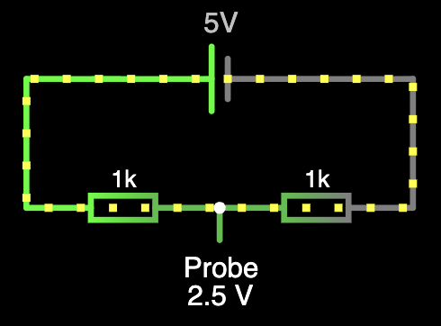
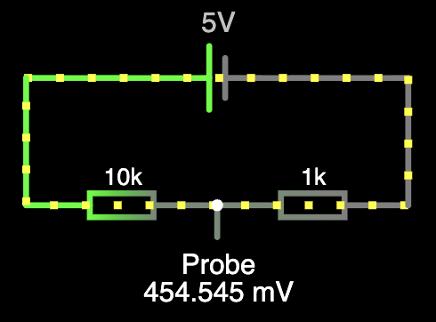
With series pathways, the voltage changes as you go along the series while the loop current stays the same, resulting in the same effect described above. Contrast this with a parallel connection; in that case it is the voltage that stays constant while the current ends up splitting. So if we put two calibrated resistors in series but tap the middle node, the $I = (\frac{V_{in}}{R_{1} + R_{2}})$ value stays constant regardless of what comes after (parallel) the middle connection. $V = IR$, and the output voltage is the voltage of the middle node with respect to the ground, it is equal to the voltage drop across resistor 2. Therefore $V = (V_{in}\frac{R_{2}}{R_{1} + R_{2}})$. Congratulations, by tapping the middle with a wire, we have a stable reference voltage! We can tweak the ration between the resistances in order to obtain the fraction of the source voltage we want.
Details
If you didn't feel something right about the constant-ness of the current like me, after doing some research, it seems to be the case that it isn't really constant. If you are wondering what I am talking about: I spoke about how the voltage stays the same at a parallel connection (middle node), so far so good, that is what we want. However I also glossed over the fact that current splits by contrast. To calculate the reference voltage we used that current ($I = \frac{V_{in}}{R_{1} + R_{2}}$). That current split, again, depends on the load on the parallel pathway! When a load is connected, its resistance sits in parallel with $R_2$ with an equivalent resistance of $R_{eq} = \frac{R_2 \cdot R_{Load}}{R_2 + R_{Load}}$. So the new formula depends on that joint parallel resistance that changes with the load: $V = (V_{in}\frac{R_{eq}}{R_{1} + R_{2eq}})$. This doesn't sound stable at all! It seems like we can't circumvent this problem, at least by using these simple passive components. However, we can minimize the voltage sag by drawing as little current as possible -- the ideal formula above holds for that exact case.
For a long time I wondered why we use two resistors to drop voltages since one technically is enough to drop some voltage. Now that I am writing about it though, it is clear why: we don't want some voltage drop, we want one that is calibrated so that we can do useful things with it. You need a parallel connection to tap into to do that since that way it is not voltage that splits (but instead current does, though we only care about the voltage here). You need a minimum of two components to be able to even form a parallel connection in the first place!

Voltage dividers have a multitude of uses, and at least one involves not burning things out, but for our use case we'll be using them in relation to the ADC (Analog to Digital Converter) present in the microcontrollers we'll be using.
Raw voltage, just like the one coming from a divider, is an analog signal, it is a continuous voltage anywhere in between 0 and whatever the supply voltage is (5V, 3.3V, etc.). Microcontrollers are digital processors, because they handle data in binary combinations of HIGH (1) or LOW (0) signals. Many simple sensors output analog values because whatever they are measuring literally cause a calibrated drop in voltage. To make sense of these values through a MCU, we have to digitize them through an ADC (Analog to Digital Converter). This is an integrated part of most MCU boards that takes in an analog signal and converts it into an integer count. Some precision is lost because digital data is discrete so ADCs operate with voltage steps (4.8mV for the Arduino Nano and 1.2mV for the STM32)
Capacitors
A capacitor stores energy in the form of an electric field, generating an opposite voltage across it as it charges. If you short it with a voltage source, it first acts as a short circuit. However, as it begins to accumulate charge, a voltage opposite to that of the source begins to develop. At full capacity $V_{source} = V_{capacitor}$ so no current flows, acting like an open switch. The ability of a capacitor to store electric charge is quantified as its Capacitance (C), measured in Farads. Caps with higher C can store more charge given a set voltage.
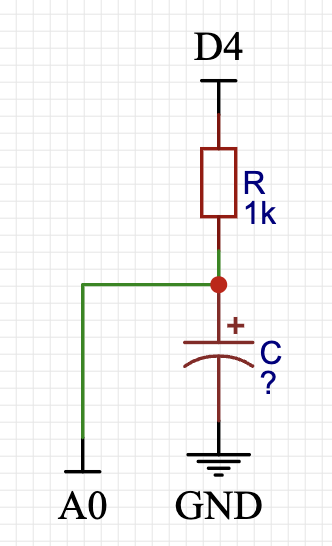
An RC circuit is just a capacitor and a resistor in series. In fact, it is just like our voltage divider configuration, instead of Resistor 2 we have the said capacitor. This way, by probing the middle node, we can measure how much voltage is across the capacitor (we will use this information later to measure C).
Imagine the scenario where the RC is completely disconnected and the capacitor fully drained. We connect the positive side of the circuit to the 5V supply of a MCU mediated by a switch and the negative side to GND. Take R = 1000 Ohm and the ADC 10-bit (counts 0 - 1023).
If we are to suddenly energize the circuit, the following things happen:
- The capacitor acts like a short circuit with a resistance close to zero. This means that the entirety of the source voltage (5V) is across the resistor. The voltage drops at the node to 0. The ADC reads 0.
- As charge builds up, the capacitor produces its own potential difference. This can be modeled by its resistance increasing with time, skewing the (1 / R1 + R2) value. Now there is a voltage across the cap meaning the resistor doesn't drop the full 5V anymore. As an example at t = $t_1$ the capacitor might have 2V across it, leaving only 3V for the resistor to drop. Therefore the middle node sees 5V - 3V = 2V. The ADC reads around 614.
- After a while, the capacitor gets charged to its full capacity. At that stage the voltage across it is 5V, leaving 0 for the resistor. The resistor doesn't drop any of the 5V so the full voltage is read as the maximum ADC value 1023.
Two important observations as well as a message of caution:
- The ADC value is directly correlated with the voltage across the capacitor. In fact. If you take the count, divide it by 1023 and multiply it by 5V you obtain exactly* the voltage across it.
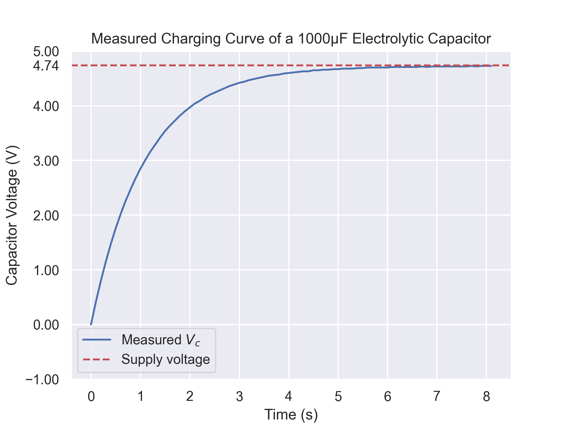
- You can't really observe this from how I explained the scenarios but the charging of the cap follows an exponential decay curve. This is because the cap charges quite fast at first but as charges accumulate on the dielectric, they themselves exert electrostatic forces on other charges trying to pile up and impede the accumulation of charge. The voltage flatlines at the equilibrium.
- We are in the real world here, so all of these processes have a lot of uncertainty, especially if you are prototyping on a breadboard with cheap MCUs. Resistors normally do not have extremely tight tolerances, there is of course the aforementioned ADC quantization but also everything from the leads to the breadboard has stray resistances, capacitances and inductances that will introduce some sort of error and uncertainty into all readings.
 (Measuring setup with Arduino Nano that streams $V_c$ back to the serial port. The supply voltage is around 4.74V instead of the 5V you would expect from a USB port, I suppose this is because of the dongle I am using.)
I obtained this data to plot this curve by toggling charging through a digital pin and repeatedly sampling the ADC and sending it back to the serial port to log it. Here's the important part for measuring C:
Capacitors with larger capacitances take longer to charge, so the bigger the capacitance, the longer it takes for it to level off.
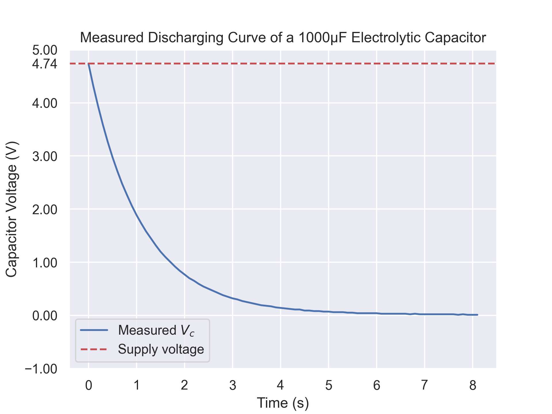
But that is sort of a qualitative measure, and we need exact numbers to compute other exact numbers (C). We'll consider the discharging case, though you can joggle around the equations below to adapt this for a charging curve.
The exact interaction between the resistance, capacitance and source voltage obey a differential equation (the more charges accumulated $\propto$ slower rate of change of voltage thing), which when solved yields the following exponential model: (when discharging)
$$
V(t) = V_0 \cdot e^{-\frac{t}{RC}}
$$
The nice thing is that we outright know $V_0$ and $R$, we can probe how much time has passed, and we have empirical measurements of $V(t)$, which means that we can figure out what $C$ is. The simplest way to work with this is to take $t = RC$ and do some algebra. Then the fraction cancels out:
$$
V(t) = V_0 \cdot e^{-1}
$$$$
V(t) = V_0 \cdot 0.368
$$
This essentially means "when the measured voltage is 36.8% of the source, the current time is equal to the sense resistance times the capacitance". We repeatedly sample for $V(t)$ and check if it is equal or less than 0.368 * V_SOURCE and for the first point we measure the elapsed time. Subtracting it from an initial measurement of time yields t.
We already knew $R$ and now know $t$ and picked a convenient $t = RC$ value so: $$ C = \frac{t}{R} $$
That's it! I know I did a lot of yapping but the circuit and calculations are quite simple. You hook up one leg of the resistor to a digital (output) pin. The other end goes to the measurement node that connects to the positive leg of the capacitor as well as an analog (input) measurement pin. The negative leg of the capacitor connects to ground.
Some important considerations for the resistor:
- Picking R too large means less current flows and the capacitor takes longer to charge, leading to more precise readings of smaller capacitors. Higher R's mean capacitors take longer to charge.
- Picking R too large will result in amplification of the effect of parasitic resistances and capacitances. For example, the leakage current of a capacitor might be too significant compared to the driven current mediated by a large R, so a cap might not even reach the full source voltage during charging.
- Picking too small of an R will distort calculations as the microcontroller has a finite sampling rate. The voltage will rise be too steep and a such changes will be less likely to be captured fast enough.
- A really small R (<250) risks damage to the MCU pins. Arduino boards (ATmega328P) really shouldn't see more than 20mA and STM32 boards 10mA to live a long life. Also more current also implies more heat losses, which sometimes might be enough to throw off readings by getting components hot.
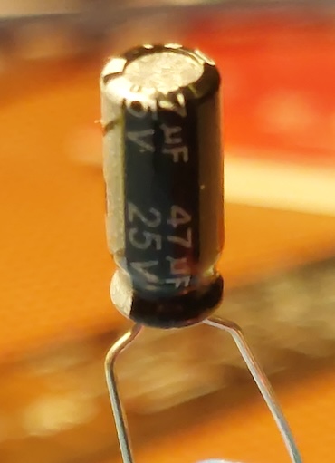
I personally use $R = 1000$ to measure electrolytics and $R = 20000$ to measure ceramics, and it works quite well for my practical liking. Though things might get a little inaccurate as you go past below 10nF.
So why am I not content with what I have right now? Well, the C value of a cap is simply not enough for many applications, especially in areas like RF and power electronics which I want to deep my feet in. Knowing the equivalent series resistance (ESR) alongside C is required. Measuring that with this RC method is of course possible, but highly prone to error due to the aforementioned parasitics. Remember how we talked about the discrete nature of the ADC? You need a really small voltage step to resolve that offset caused by the ESR that you cannot reliably detect with RC timing.
So next, we will (and I mean we, because I have no idea how this really works) look into how commerical LCR meters do capacitance and ESR measurements. It involves a high frequency AC method.