Since I started building thing I have had a lot of things go wrong in my life. First my soldering iron broke down. Then I spilled my entire bottle of no clean flux everywhere and had to resort to weird chemical treatments so that things wouldn't reek of rosin for a long time. Shortly after my phone's motherboard burned out. I had to finish this in time before any other bad things happened!
I recently managed to get a hold of a package of the DSO138 DIY and assembled it myself. It's a nice little thing and is pretty darn accurate, at least for the things I am using it for. However, there is one large problem: electrical noise. There is a lot of it and at some points I don't know what is noise and what is signal.
Now I don't 100% know where this is coming from. It may be coming from the power supply, the supply of the signal itself, the probes picking up unwanted stuff or the scope might just be doing that (it is 30x cheaper than commercial scopes after all). But I believe it is a large part due to the scope power supply because it is an SMPS I got for really cheap online. It is probably spewing EMI everywhere and what the scope might be mostly due to its switching noise.
Unlike many of my other posts, I won't structure this one like a tutorial, instead just document my build process and things. But honestly building a linear power supply looks so damn simple that I don't need to elaborate much.
The Goal
My goal is to take the 230VAC from the mains and do some things to it so that we obtain a low voltage DC supply. Long before power electronics how ubiquitous were linear power supplies that did this job simply and cleanly. However simply doesn't mean cheaply and it certainly doesn't mean compact. All of the big bulky components like the transformer and big capacitors required are large, heavy and expensive. Switch mode power supplies (SMPS's) changed everything, because now you could shrink your previously bulky components and more complicated (but this time smaller!) feedback circuitry with them. SMPSs are the reason a charger can be smaller than the diameter of a receptacle and not have to be a large rectangular prism sitting on a bench.
However, they are notoriously difficult to get right. Linear supplies on the other hand are dead simple in comparison. Plus no matter what precautions you take, SMPSs always leak some switching noise into mains as well as the thing it is powering. These precautions are more voluntary the cheaper you go. Linear supplies on the other hand are extremely quiet when it comes to this -- they leak no switching noise (because they don't switch) and very minimal mains noise. Here my goal is to build a linear power supply that can continuously deliver a stable voltage, adjustable from 3.3V to 12V up to 1A.
Details
There is also the fact that if I were to design a switching power supply it would be a glowing fire and shock hazard.
The Design
The classic design goes:
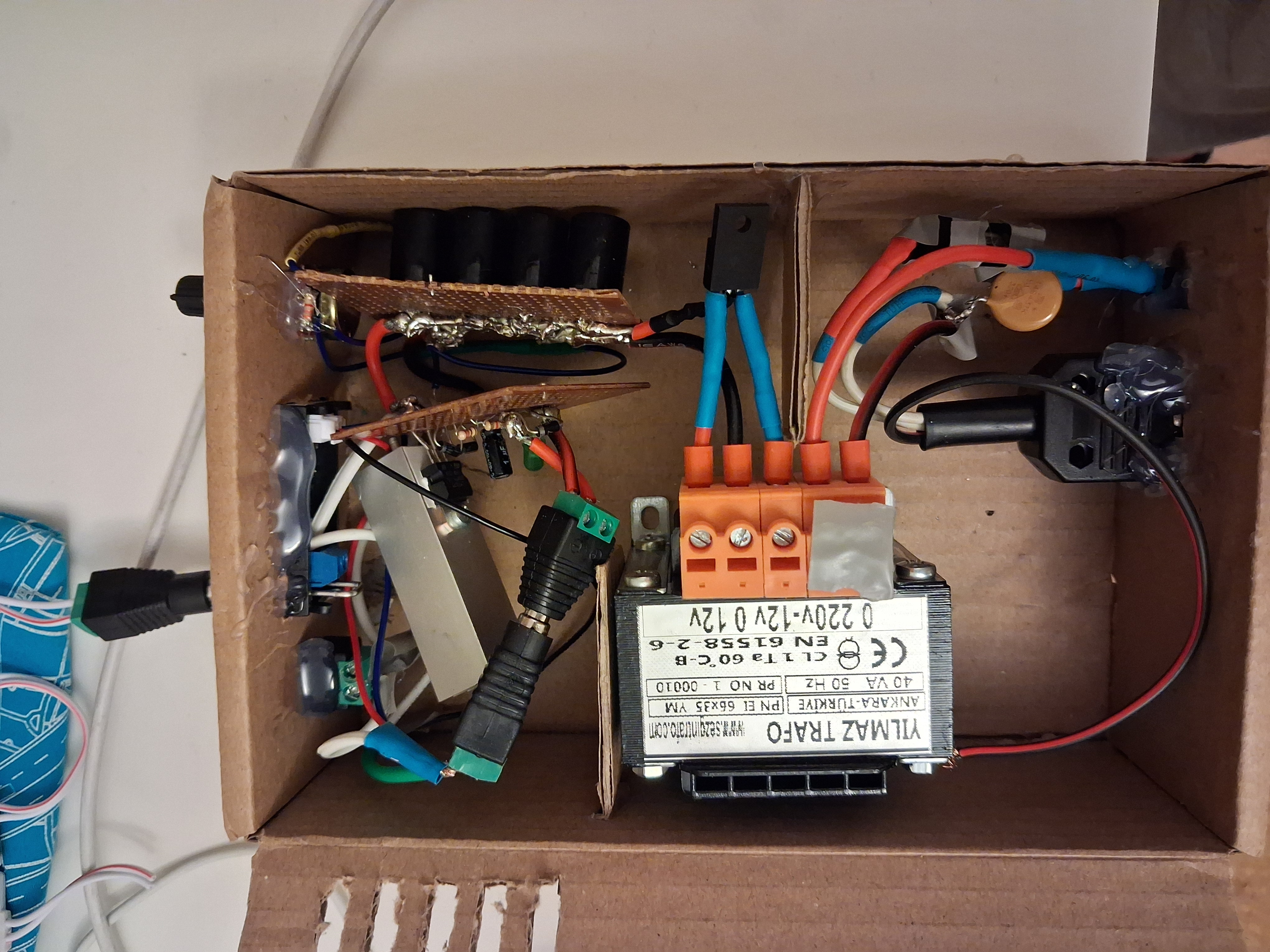
Mains AC -> Transformer -> Rectifier -> Capacitor Bank -> Regulator -> +DC
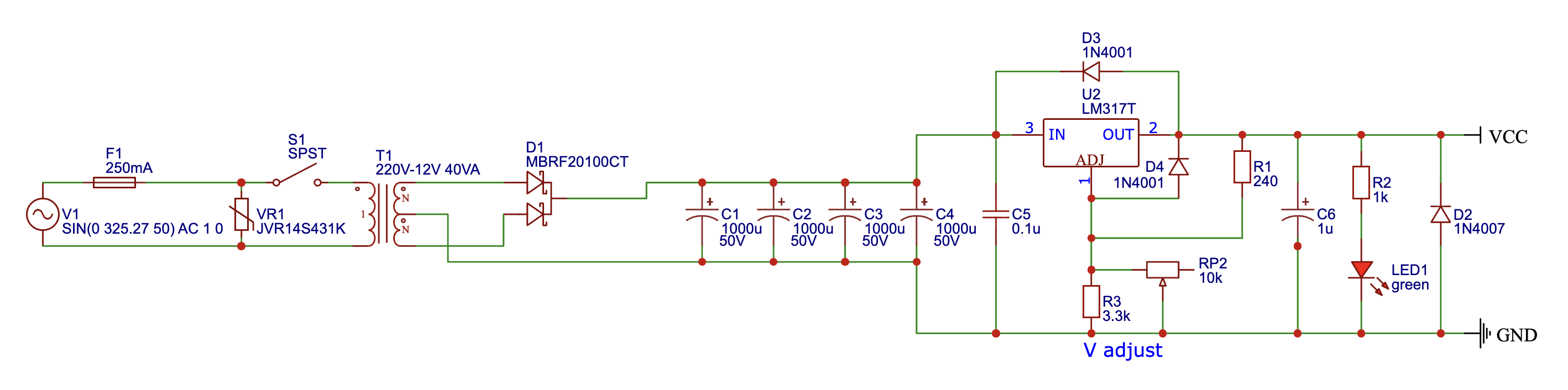
The tranformer steps down the voltage, the rectifier turns it into pulsed DC, the capacitor bank smooths it out and the regulator regulates it to a set voltage. I designed the following schematic for it:
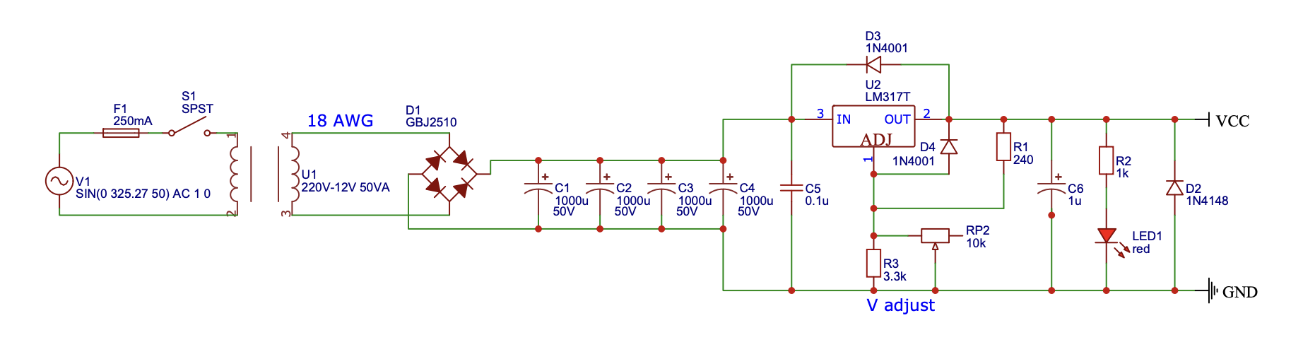
Some things worth explaining:
- I am using four 1000uF electrolytic capacitors in parallel for a total of 4000uF to get a really smooth rectified DC signal. This much is probably overkill in a good way!
- You might have seen classical designs that use fixed voltage regulators like 7812 or 7805 but I wanted to push myself to bear the slight complexity of using an adjustable regulator (LM317). The voltage is determined by the ratio of the "V adjust" resistance to R2. The 3.3k in parallel with the 10k pot results in an approximate voltage range of 1.25V to 14V, mostly in range of what the capacitor stage can provide.
- There are three protection diodes in the circuit. The two slow-acting diodes are there to prevent the capacitors from discharging backwards through the LM317 and risking damage. The one across the output terminals is to deal with inductive loads that generate opposite polarity flyback voltage like DC brushless motors and relays.
Real Loads
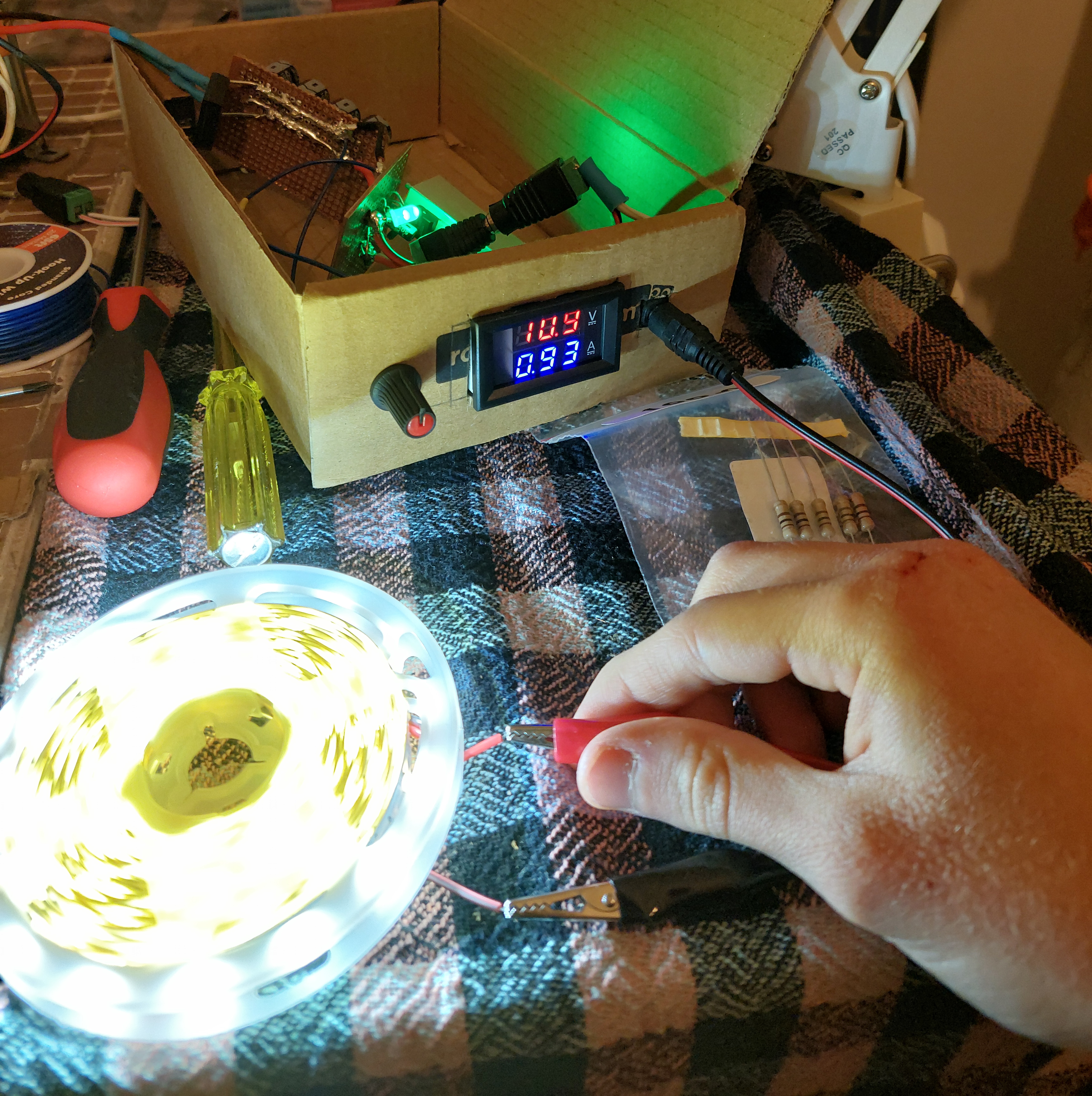
It definitely works! I can adjust it with the 10K pot to go from 1.25V to... 14.4V? Not exactly 14V, and I probably got some calculations wrong but 12V is in the range so I am not complaining.
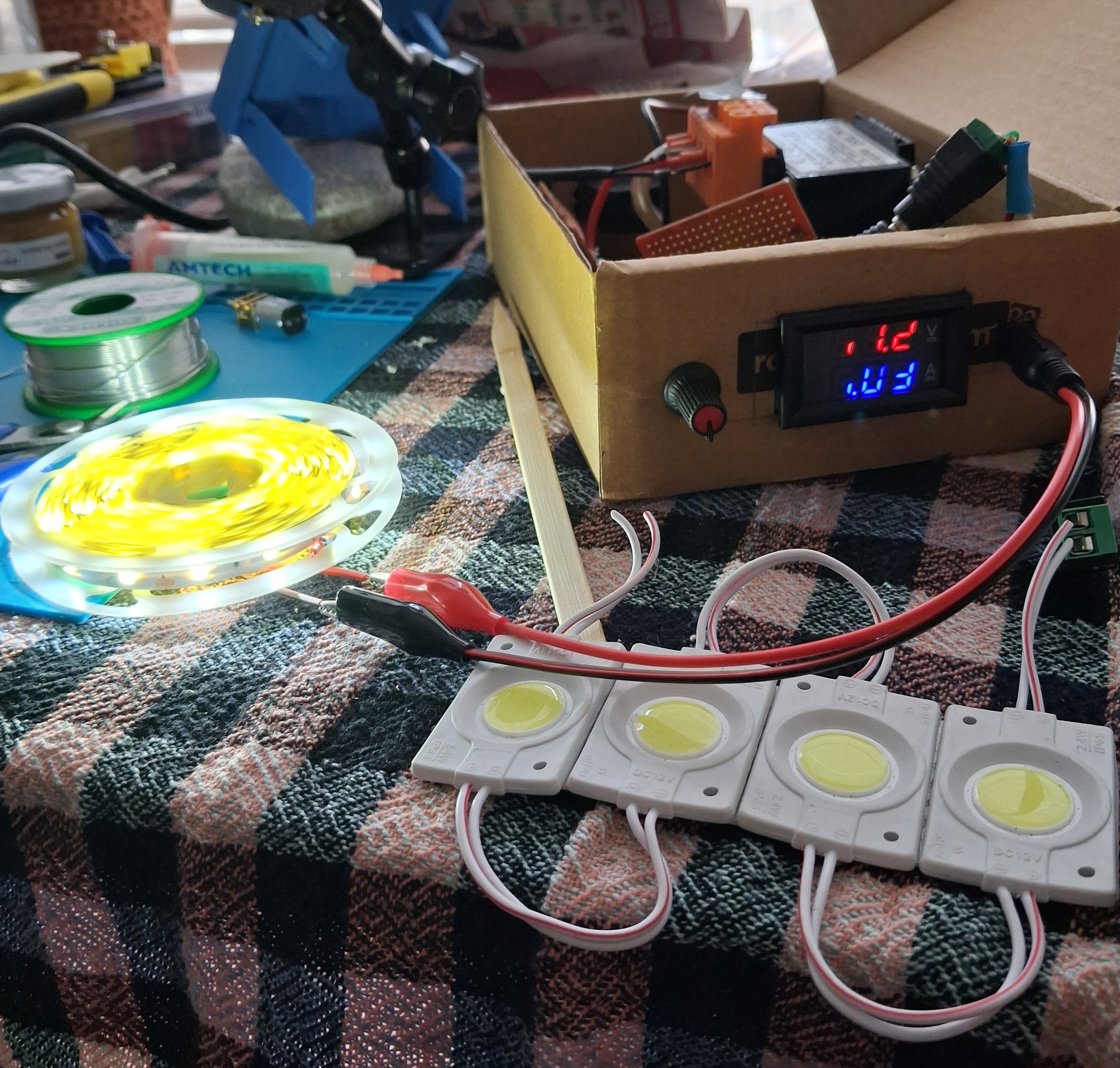
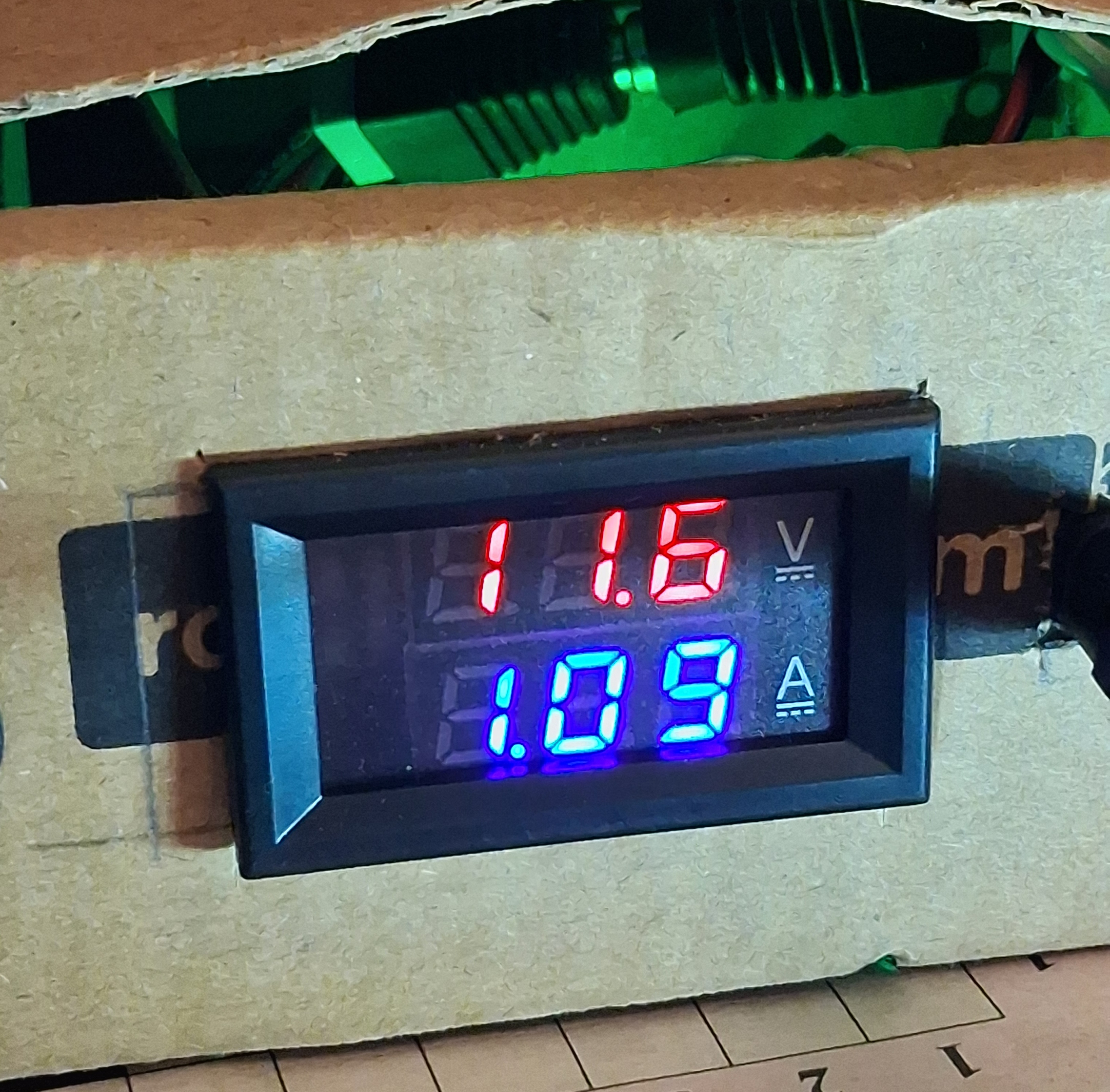
To test it I set it to 12.1V and plugged in a 12V test load LED strip that pulled 0.5A. What I noticed first was that the voltage sagged substantially to around 11.5V. Not enough to mess with the LEDs and I could adjust it again to 12V but it didn't feel great.
Next then I plugged in an even longer LED strip that pulled around 0.93A, basically my claimed capabilies. However, to my dismay, the ammeter read 10.9V! That isn't at all acceptable. Worst of all, adjusting the dial all the way didn't change anything. It would just oscillate between 10.9V and 11.1V.
There's clearly a bottleneck here, and that certainly isn't the bulky transformer rated for 50VA (~4A @ 12V). So I needed to debug downstream. I am currently away so I cannot probe things physically right now but I can at least calculate.
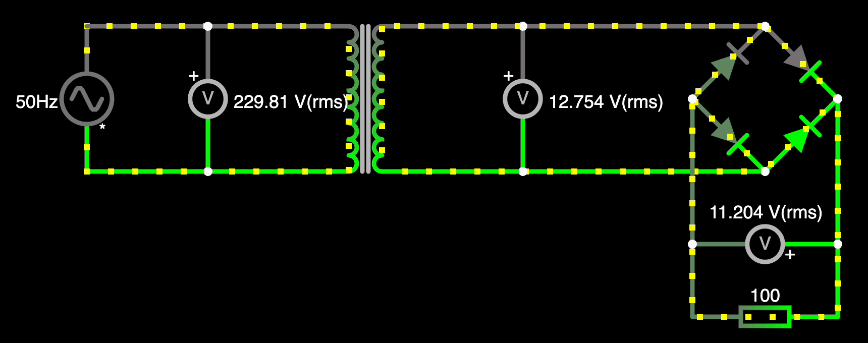
The tranformer is a step down transformer for 220V to 12V, that is how they make them in the industrial district. However our mains is more around 230V here so I have no idea why they make it that way. Measuring the floating voltage on the secondary thus yields 12.8V. Though this probably sags when loaded, so 12.5V might be a decent estimate to go forward.
Next is the rectifier, and with hindsight this is where the problems lie. All diodes have a voltage drop across them that is needed for them to start conducting. In my case, the full bridge rectifier package I am using has a voltage drop of 1V for one diode. So at each cycle the resulting RMS voltage is around 10V RMS, pulsing between 6V and 14V! The big bank of capacitors makes the signal such that the peak to peak signal gets smoother. These caps also act as buffered storage so that the actual voltage across them is the peak voltage they receive. This is because they fill to the peak voltage with time as they are currently unloaded. $$ peak(10V_{RMS}) = 10 \times 1.414 \approx 14.4V $$ That explains why I see that exact voltage on the voltmeter! But this is "phantom" voltage that should quickly dissipate when loaded. The more I lower the voltage the "phantomness" of the voltage should reduce until I reach 10V, the actual capability of the supply at the moment, in which case I can pull 1A without much sag.
The voltage drop across the rectifier goes straight into heating it as expected. In fact it gets as hot as the regulator! The regulator does have a decent heatsink attached but still I am burning off considerable voltage before things even reach the rectifier and I can't supply enough power to the actual load.
Some Diodes Are Better Than Others
It is clear that this bulky rectifier with a hefty 2V total forward drop should go. But what will replace it?
Schottky Diodes
The rectifier package is made of regular diodes, however those have a high voltage drop to state it for the last time now. Schottky diodes on the other hand have a considerably less forward voltage drop. They have disadvantages like lower current and reverse voltage ratings, etc. Though the 1N5822 seem like the perfect widely available diode with acceptable ratings for this supply. Each of them has a forward voltage drop of around 0.45V. So one cycle will drop 0.90V instead of 2V. Already much better. The heat dissipated by them is also less as power is proportional to voltage drop.

Transformer..?
Wait, didn't I say that the transformer may be the most reliable part of this whole supply? I didn't exactly say that, but it is. It was relatively expensive but it is thoroughly isolated and the 50VA figure is a 24/7 reliability figure -- I went down to the district today and talked to the craftsman again and he said it can reliably pull 65VA for an hour.
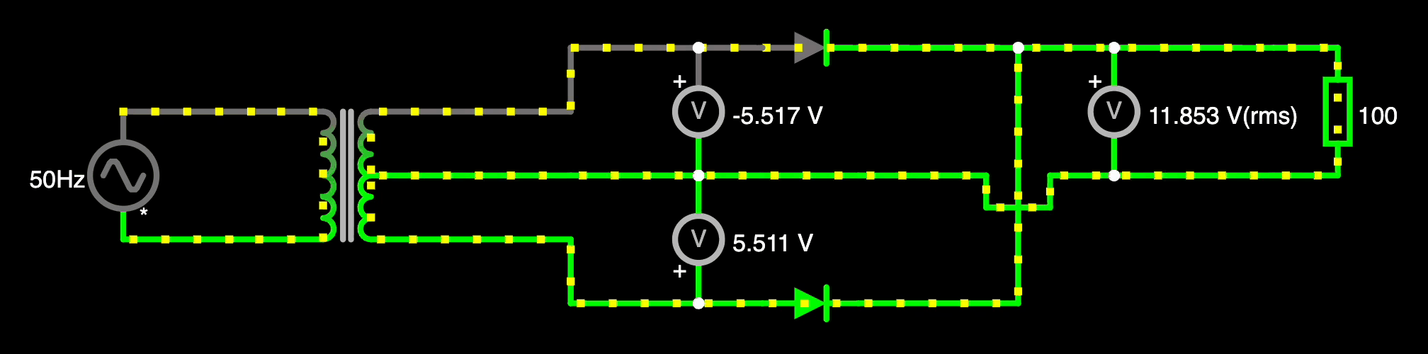
However the reason I went back there is ironically because I wanted to get a new transformer with a very different topology. I got a 40VA one this time because it is plenty powerful but also small enough to fit in my cardboard box, but also center tapped. You see, a regular transformer has one continuous primary coil and another continuous secondary coil. The primary generates an alternating magnetic field that induces EMF on the secondary. To full-cycle rectify it you need a total of 4 diodes because you need a return path that also has to be polarity protected. For example the positive half-cyle takes one diode to actually rectify and then another for the return path. The total full bridge rectifier requires 4 diodes and at each time there are two diodes conducting.
Now take the transformer and right at the center of the secondary coil and add a tap there. Now if you measure the voltage between the start of the coil and the center tap, you get $\frac{V_{secondary}}{2}$ (RMS), where $V_{secondary}$ is the original potential difference between the two ends of the transformer. This is because the induced voltage depends on how many turns the secondary has, and you get half of the voltage when you have passed through half of the turns by the time you are at the tap. Now if you measure from the center tap to the end of the coil you also get $\frac{V_{secondary}}{2}$ (RMS) because it is also exactly half the distance.
What makes this extremely useful is that voltages are relative -- voltage means a potential difference in the electric field per unit charge, so if you adjust all voltages at the same rate you don't physically change anything! I'll give an example over a 12V center tapped transformer. The actual full secondary is made for 24V, so specifying from the start of the secondary coil the RMS voltages are [$0$, $12V$, $24V$]. However if you treat the center tap at $\frac{V_{secondary}}{2}$ as the zero point/ground, you get [$-12V$, $0$, $12V$]. As we artifically negate the voltage on one side, the two AC voltages, each at $12V$, are actually identical but 180 degrees out of phase. This means one side is always conducting while the other returning. We don't have to polarity guard the returning path anymore -- what we have is a center tap, a universal return path, that doesn't need to care about polarity. The AC current always goes back there in one direction no matter at what point the cycle is at. This means we just have to enforce polarity once per half-cycle = only two diodes needed = half the voltage drop!
Details
The old transformer isn't just sitting there idlely, I am using it again to get more data for my Physics IA so it is a good thing that I have a transformer not needed to be disconnected.
So we can reduce the forward voltage drop of the rectifier from 2.2V to 0.45V and therefore the heat dissipation as well!
Worse Schottky Diodes!
While at the industrial district I went ahead and grabbed the aformentioned 1N5822 from a component store. However when I came home to organize everything, I realized they were 1N5819's instead! They are basically the same thing but with a smaller package (= worse heat dissipation) and an amperage rating of 1A! (contrasting with the 1N5822's 3A) That is very borderline so to test the center tapped configuration I decided to use my regular 1N4007 diodes with a nominal voltage drop of 1.1V instead. That is still half the drop compared to the original transformer + full bridge rectifier so I was expecting much better performance.
The highest voltage is 14.9V now compared to the previous 14.4V.
Powering the LED strip now yields a sag to 11.2V - 11.3V, still not good but borderline acceptable. The diodes run relatively hot. A diode's voltage drop decreases with its temperature so you can call them self-regulating if you are adventurous enough, and diodes are designed to run hot , but I am not sure if I am comfortable with 100C+ in a cardboard box.
The Big Gun
I forgot I even bought this thing. Very early on in my electronics learning journey I was learning about different types of diodes so I decided I would get every single type at hand, in case I need any of them! Schottky's are one such type. At this particular site I shopped from, the only one[s] I could find was this dual Schottky TO-220 package.
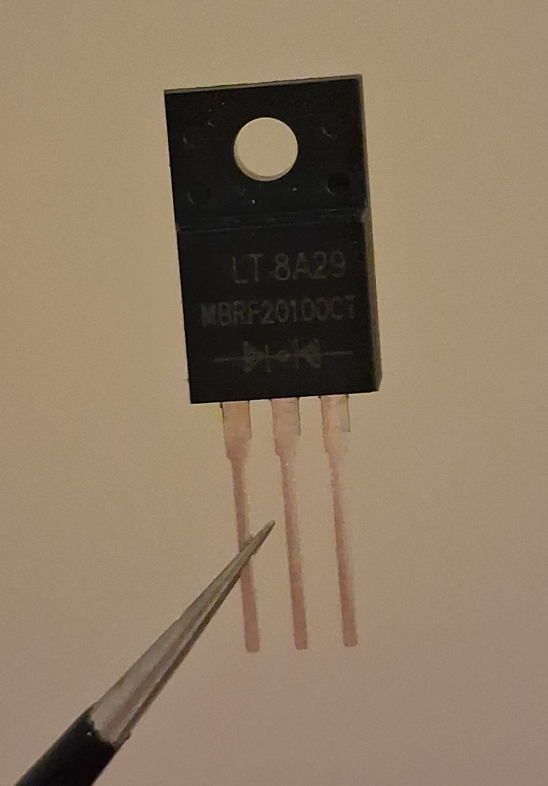
If I actually knew what a typical [axial] diode looked like, I probably would have skipped buying it believing that it was a niche component for a narrow band of tasks, but as I didn't know virtually anything back then I got it anyway. Four months later I do have a perfect use case for it!
This component, MBRF20100CT, is package containing two Schottky diodes specifically made for power electronics and switching power supplies. I am building a linear supply, but what really matters are its voltage and current ratings which are a whopping 100V and 20A. This is vastly overkill for a measily 1A supply like this, but overkill is definitely better than borderline when it comes to these things. MBRF20100CT Datasheet
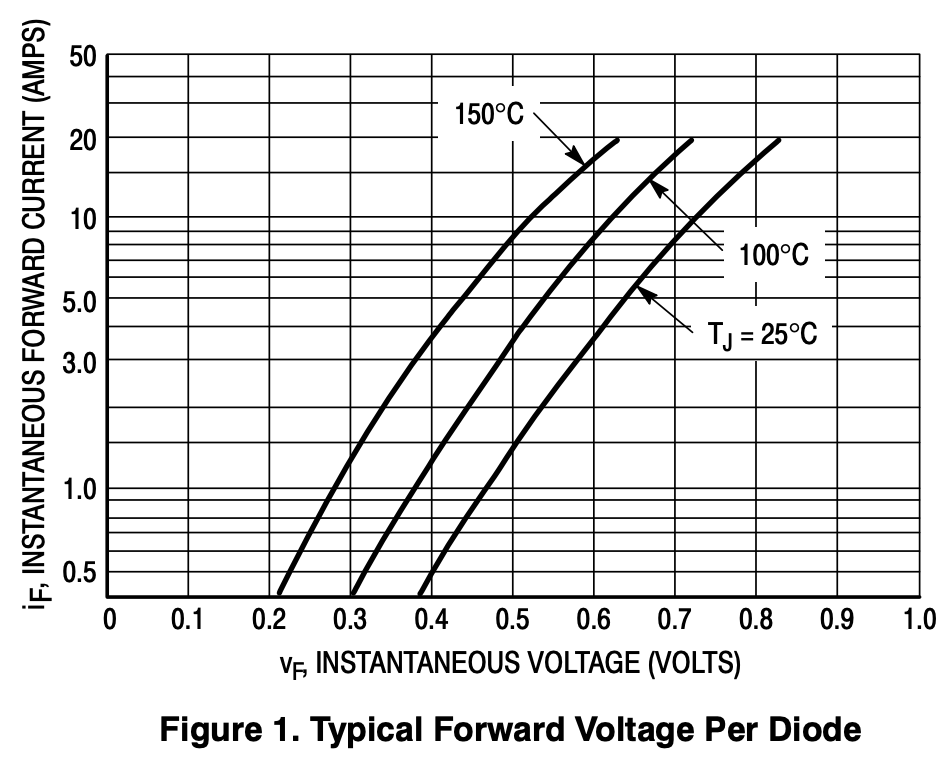
As it is a Schottky it has a much lower forward voltage drop compared to regular diodes. This chart shows the relationship between the current each diode in it is conducting and its forward voltage dropped, adjusted for different temperature baselines. At room temperature ($T_j = 25C$) each diode has a voltage drop of around 0.45V. So with a cold start it acts as a tiny heater with a power of $0.45 \times 1 \approx 0.45W$. The packaging makes heat dissipation much more efficient compared to an axial package so a reasonable equilbrium temperature may be $40C$. Linearly interpolating the temperature curves and then back tracing $1A$ with the new $40C$ curve yields something around $0.42V$. That is really efficient for a diode rectifier.
Here is the final schematic. I also added a metal oxide varistor (MOV) to add surge protection because I had some at hand.
Now actually swapping it in...
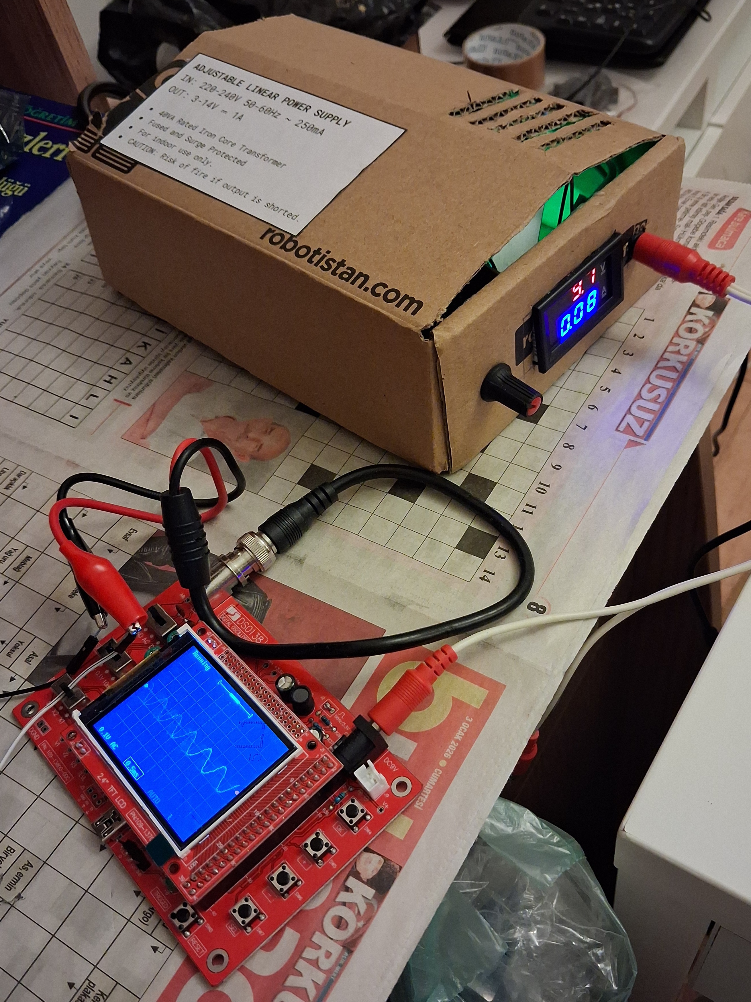
The Culmination
...and there we have it! 11.6V, an acceptable voltage for an advertised 12V, supplying slightly more current than previously to the same LED strip. It occasionally sometimes occasionally swings between 11.3V - 11.7V but this is vastly acceptable for my actual use case: You may have forgotten it by now (because I did and remember just now) that my original reason for building this was that I wanted an electrically quiet power supply to use with my DSO138 oscilloscope to minimize noise as possible, unlike cheap wall wart power supplies that are happy to inject switching harmonics to the supply rail. The scope doesn't pull anything close to 100mA let alone 1A so I expect it to be very stable.
But the real test is to figure out if the thing actually reduces noise on the scope. For reference, these are the graphs powered with the wall wart SMPS:
Just plugged in, no signal
Sinusoid generated by a microcontroller and RC filter
I set the supply to 9.1V. These are its graphs:
Just plugged in, no signal
Sinusoid generated by a microcontroller and RC filter
I virtually cannot see a difference that matters with my untrained eyes. So the verdict is... it doesn't matter to a large extent? Both signals (or lack thereof) still have that high frequency noise in there for some reason. So it should be something else other than the oscillosope power source and also the microcontroller power source. Maybe it is from the PWM signal the MCU generates itself? Maybe it is induced AC from all of the appliances in my room? It already says 0.1AC in the corner. But the noise looks higher frequency so I honestly have no idea. Please contact me if you have the answers!
So what?
I may have sounded very critical and disappointed in my remarks, but the truth is much more different than that. First of all, I did not have an adjustable voltage supply at all before! If I precisely need to power something that needs 7.4V for example, I can easily do that now. In fact the DSO138 is recommended to be used with a 9V supply, not 12V like the previous wall wart I used. So I am not cooking its LDO anymore.
But the real gains I've had are much less materialistic.
I in fact did not begin this project with the goal of having myself a bench power supply and DIY'ing it to make the cost lower . The reality is that I had obtained a bulky transformer for nothing more than for my Physics IA experiment for a topic my teacher recommended. Only when I watched this video much later that I decided I would go forward with building a linear power supply. Everything just felt so elegant that I thought I can and should build this! So much in fact that I went ahead and bought a second transformer that used not for the sake of note some numbers down on a spreadsheet. Some highlights that my learnings aren't limited to:
- I furthered my circuit diagram making skills and got more used to electrical CAD software.
- I learned how to effectively solder two wires together and apply the correct sort of heatshrink over them. I use lead-free so I was on hard mode trying not to cook the bulk capacitors in the process of soldering in a rectifier leg.
- I learned not to use liquid flux and instead use paste and solid rosin because the liquid stuff just didn't work at all for me
- I learned how to parse component datasheets. What do you mean that there is a document out there has a component's specs, model wiring with complementary components and what package leads correspond to what!?
- I actually learned how to use crimp terminals -- it is definitely harder than it looks! If I had not bothered with safety (grounding, crimping, heatshrinking, even taping) to this extent this project would have taken half of my days effort of soldering, things not working, desoldering, things not looking right, redrawing, resoldering, and on and on and on... I even added makeshift cardboard insulation to further seperate the high voltage rail from the low voltage rail.
- I learned that A MOV is wired in parallel with mains after the fuse
- I learned how to use a hot glue gun while making a little mess in the process
I also alluded to a bunch of unfortunate situations I have been in since starting building this thing. First my soldering iron broke down. Shortly after I spilled my entire bottle of no clean flux everywhere and had to resort to weird chemical treatments so that things wouldn't reek of chemicals for a long time. Shortly after my phone's motherboard burned out! I know this is pure superstition but there is a sense of calm in knowing that the thing that seemingly "started it all" is over and does its job well!
And this statement...
Unlike many of my other posts, I won't structure this one like a tutorial, instead just document my build process and things. But honestly building a linear power supply looks so damn simple that I don't need to elaborate much.
...turned out to be hot garbage. I will probably have to keep banging my head over and over again, for my apparent shortsight to not foresee that there is a very likelihood of future unforeseen problems that will plague me for more weeks than my foolish past self carelessly assumed. Hopefully less though!
Don't get me wrong, this thing is an absolute fire hazard because it has a regulator that regulates by burning off power in a cardboard box. But I had a lot of fun building it and leared a lot in the process. This fills me with the same sort of accelerated beginner joy that I first experienced a decade ago with software and programming. I will be strictly using this under my provision as it will mostly stay on my tinkering desk to power the DSO138 along with some other modest things.
Some day I will revisit this thinking, "what sort of fool was I to do it like this" and "this is really cute and decent" at the same time.